getting started designing a shoe last
To design your first last can take some practice, but once you get used to it you can design lasts very quickly. This guide will help you get started. While using the beginners mode it is still possible to make all corrections manually as well. To see how this is done check the last designing manual with beginners mode off.
LutraCAD Last makes use of a template model and will merge it with a 3D scan of a foot. From this model the toe model shape and sharp edge will be used. We recommend to digitize your own last, add it to the library and use this as a basis. This way the last will already have properties you prefer.
The idea behind the software is "what you see is what you get". If you want to use a part of the template model "push" the part of the foot scan inside of the template and if you want to use a part of the foot scan "push" the part of the template inside of the foot scan.
Time to finish: 30 minutes
Required: A 3D scan of a foot
Required: LutraCAD Shoe Last software
Step 1
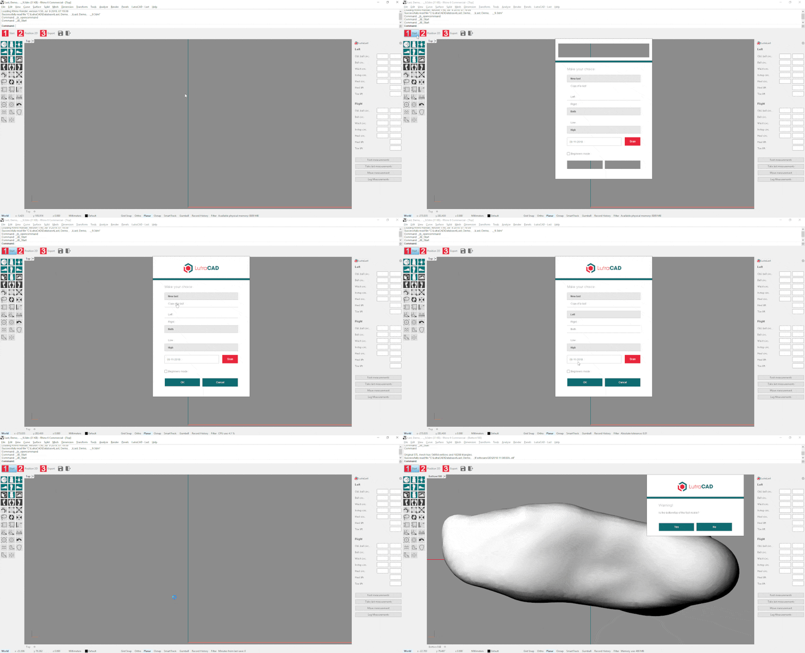
To start designing a last based on a 3D scan we start by following these steps:
- Click on step 1: Start
- Choose what you would like to create. We chose:
- New Last
- Left
- High
- Check beginners mode
Step 2
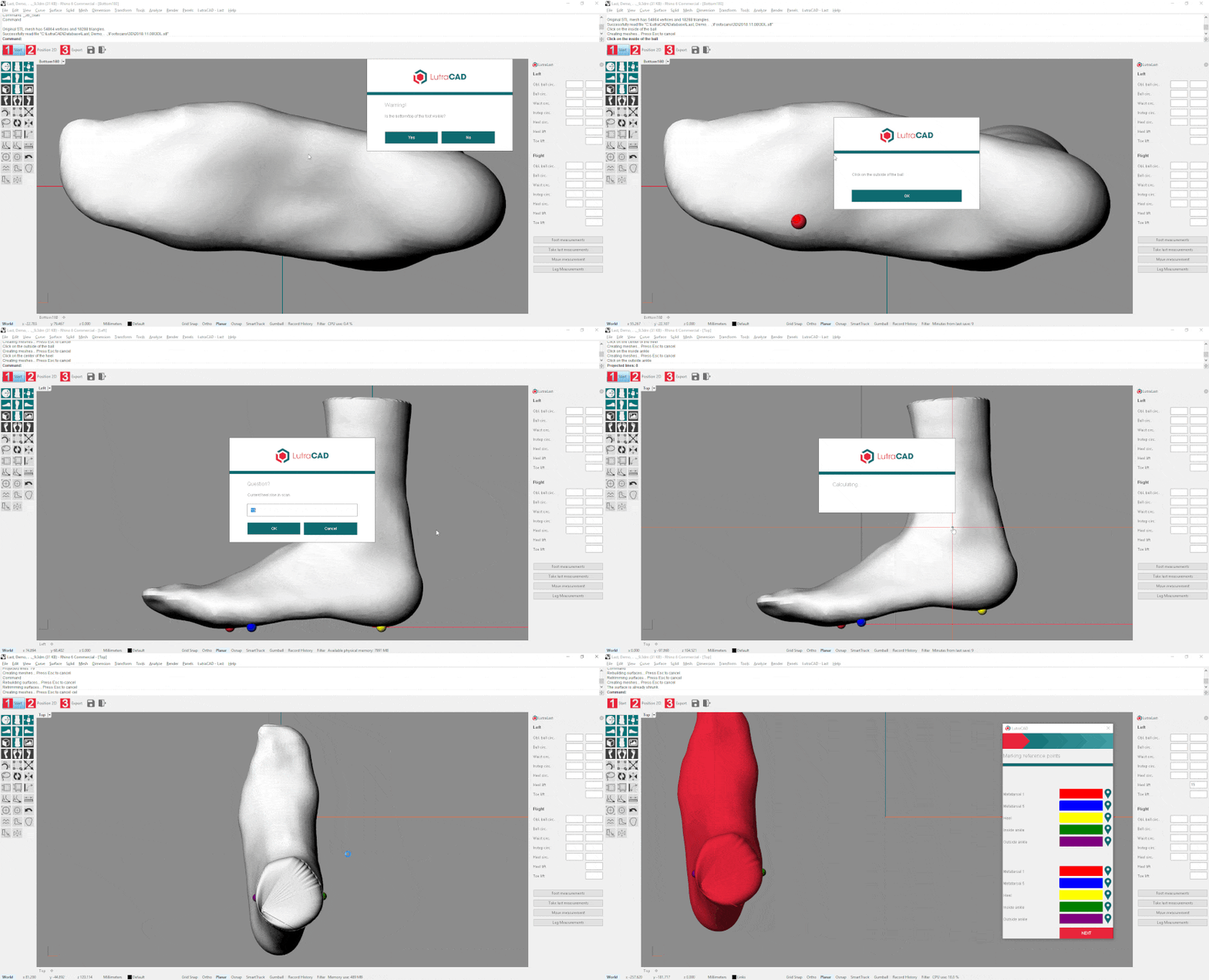
The software will ask if you see the bottom side of the foot and will then ask for 5 points and what heel lift should be used:
- Metatarsal 1
- Metatarsal 5
- Center of the heel
- Fill in the heel lift
- Medial ankle
- Lateral ankle
This will start with left and followed up by the right side.
Step 3
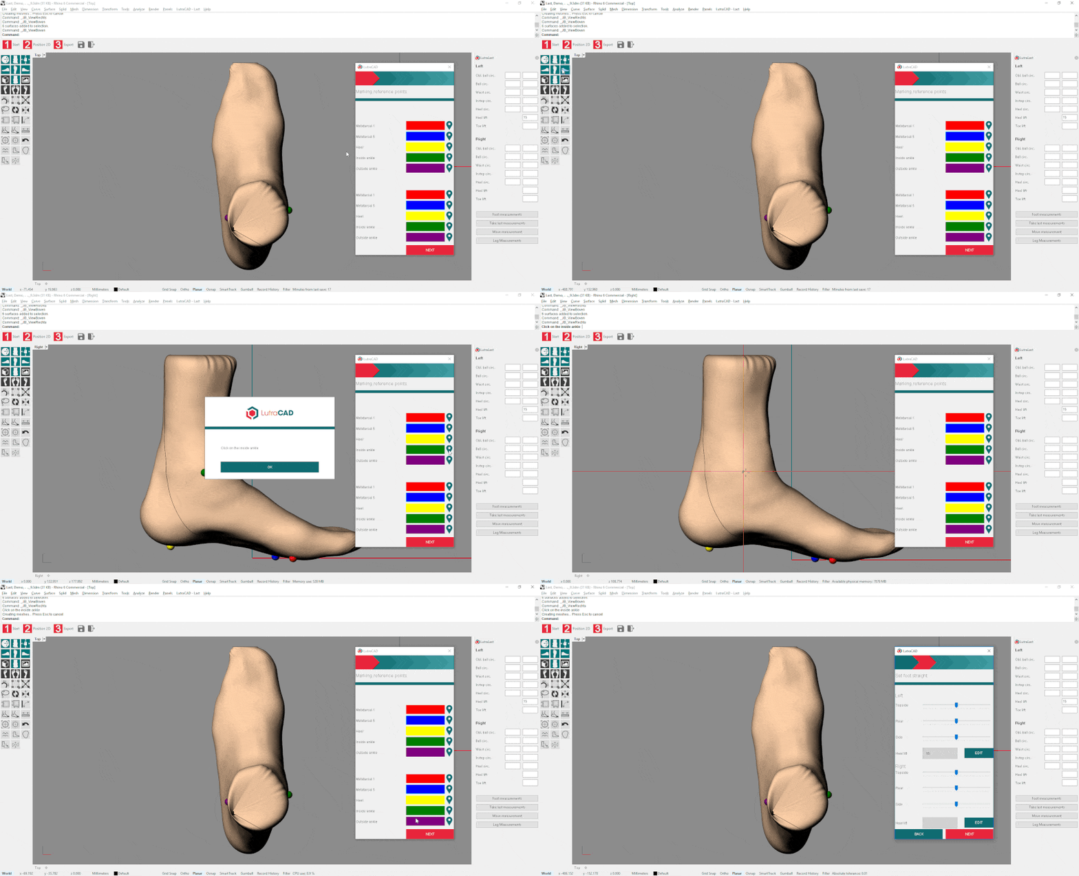
In the first dialog it is possible to reposition the markers, if not positioned correct:
- Click on the marker next to the color of the concerned position
- The screen will rotate to the corresponding view
- Click on the new position for the marker
To go to the next step click "Next".
Step 4
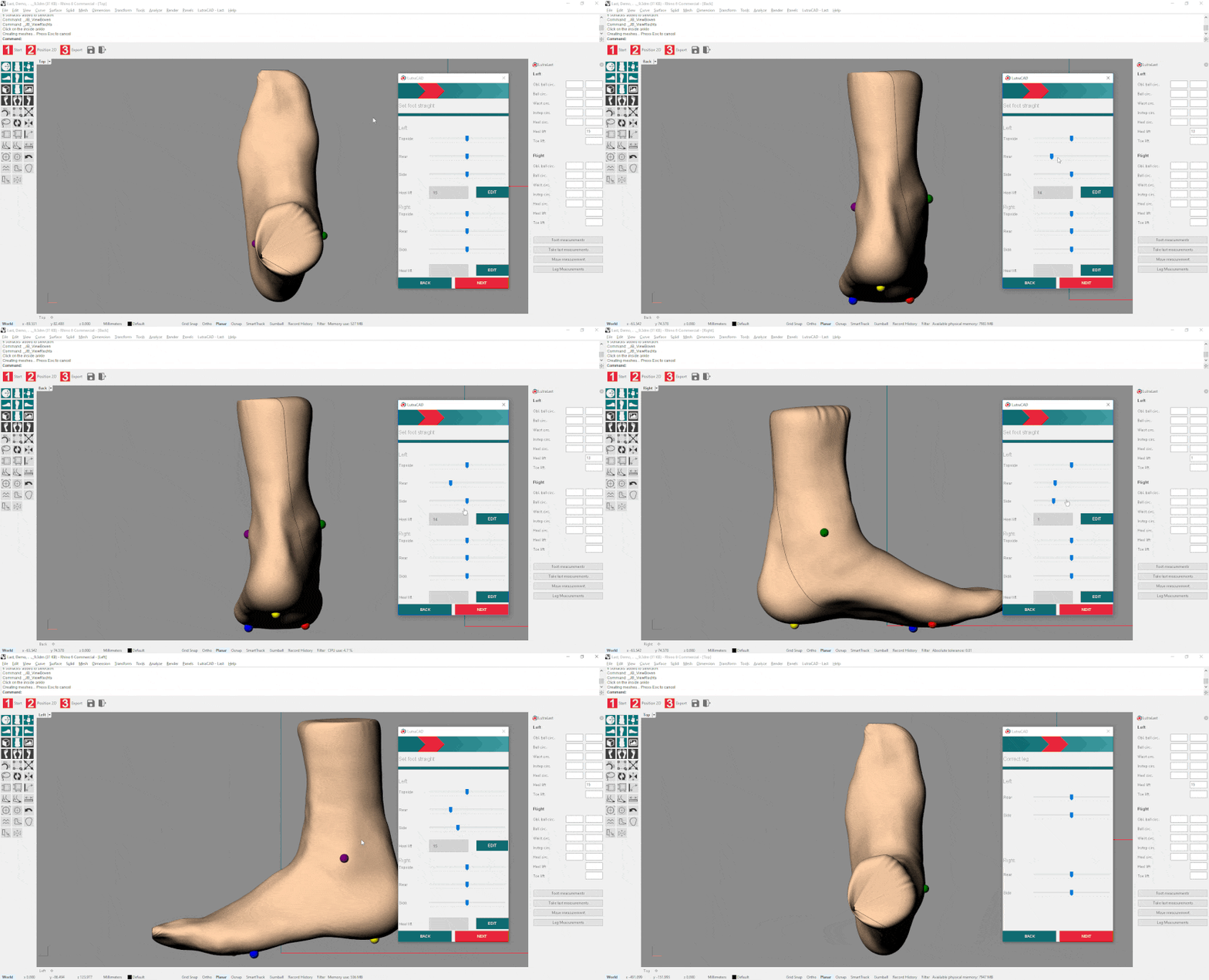
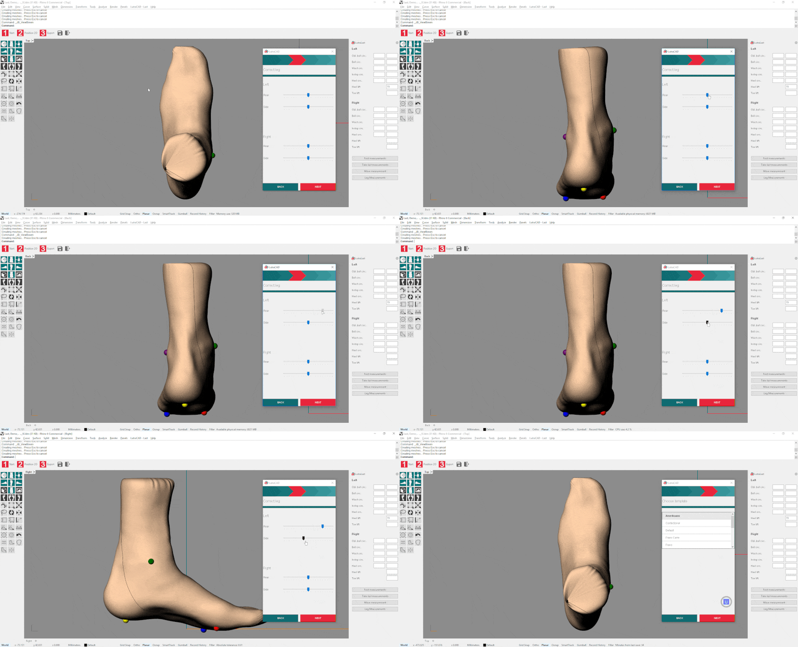
In this dialog the foot can be rotated from the top, rear and side view:
- Click on the slider for the view that needs to be checked
- The screen will rotate to the corresponding view
- Drag the slider to the left or right to rotate the foot scan
The foot will only be rotated. In the next step the leg angle can be corrected. After rotating it is possible the heel lift is not correct anymore and can be set again by:
- Clicking on "Edit" next to heel lift
- Fill in the correct heel lift
When positioned correctly press "Next" to go to the next step.
Note that the heel and toe lift will be calculated from 0. As a reference the red Axis line from the side views is 0.
Step 5
These sliders will NOT rotate the foot scan, but will make an adjustment to the angle of the leg.
- Click on the slider for the view that needs to be checked
- The screen will rotate to the corresponding view
- Drag the slider to the left or right to correct the angle of the foot
If no corrections need to be made simply press "Next" to skip this step.
Step 6
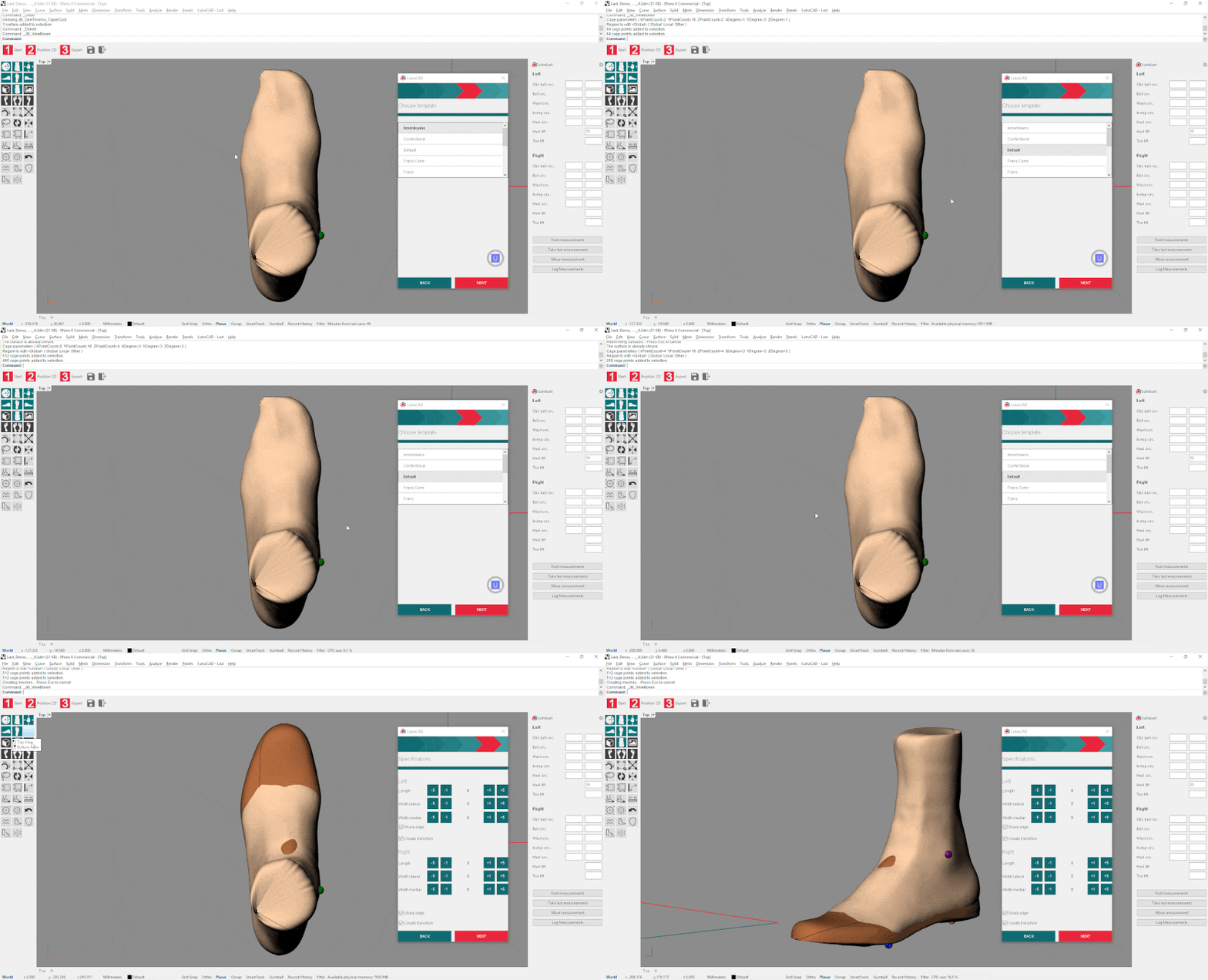
Our next step is to choose a template model that we want to use as a basis.
- Select a template model
- Click on "Next"
- The software will automatically adjust the template model to the shape of the foot scan.
Step 7
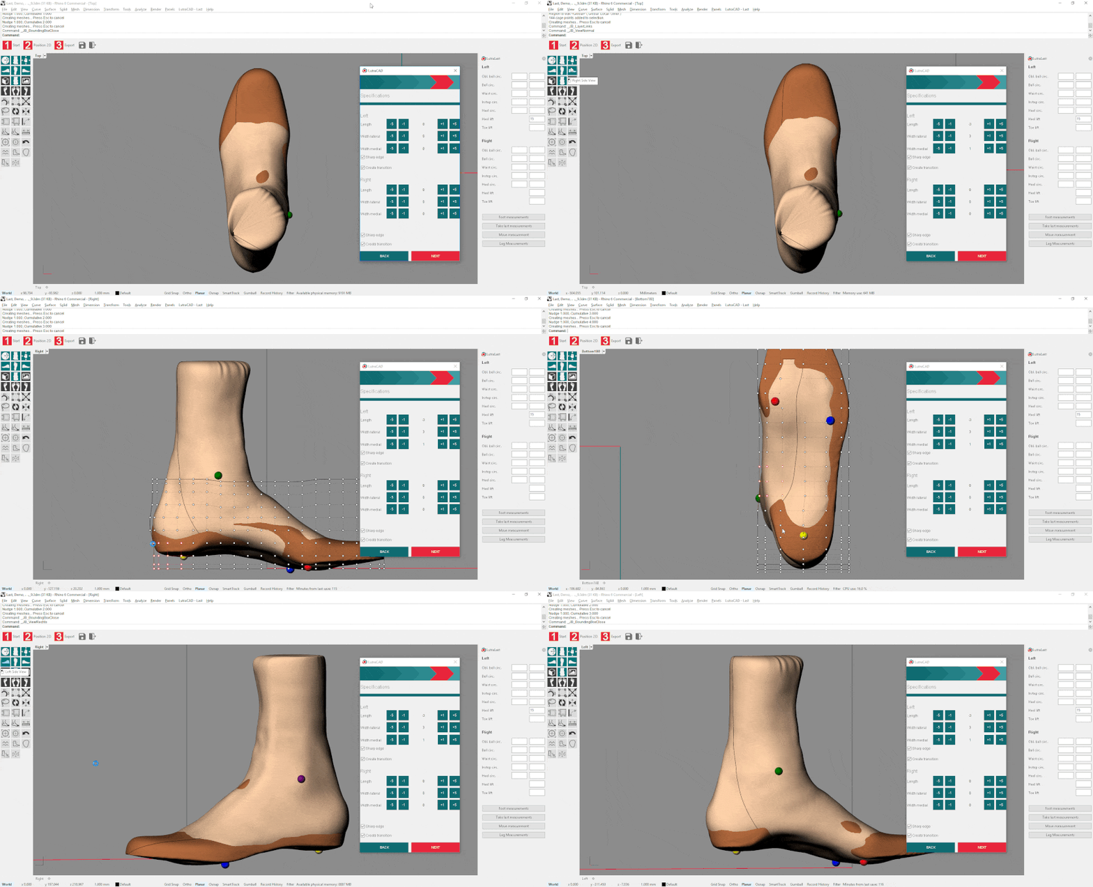
By clicking the - and + buttons it is possible to increase/decrease the length or width of the toe model. This can also be accomplished by using the BoundingBox.
With the 2 checkboxes you can enable/disable the sharp edge and if the software needs to make the transition between the foot scan and the template model or not.
This is also the step to check your model and "push" the parts inside you do not want to use, because if "Next" is pressed the software will merge these parts together. Clarification: the brown part is the template model and the nude color is the foot scan.
Step 8
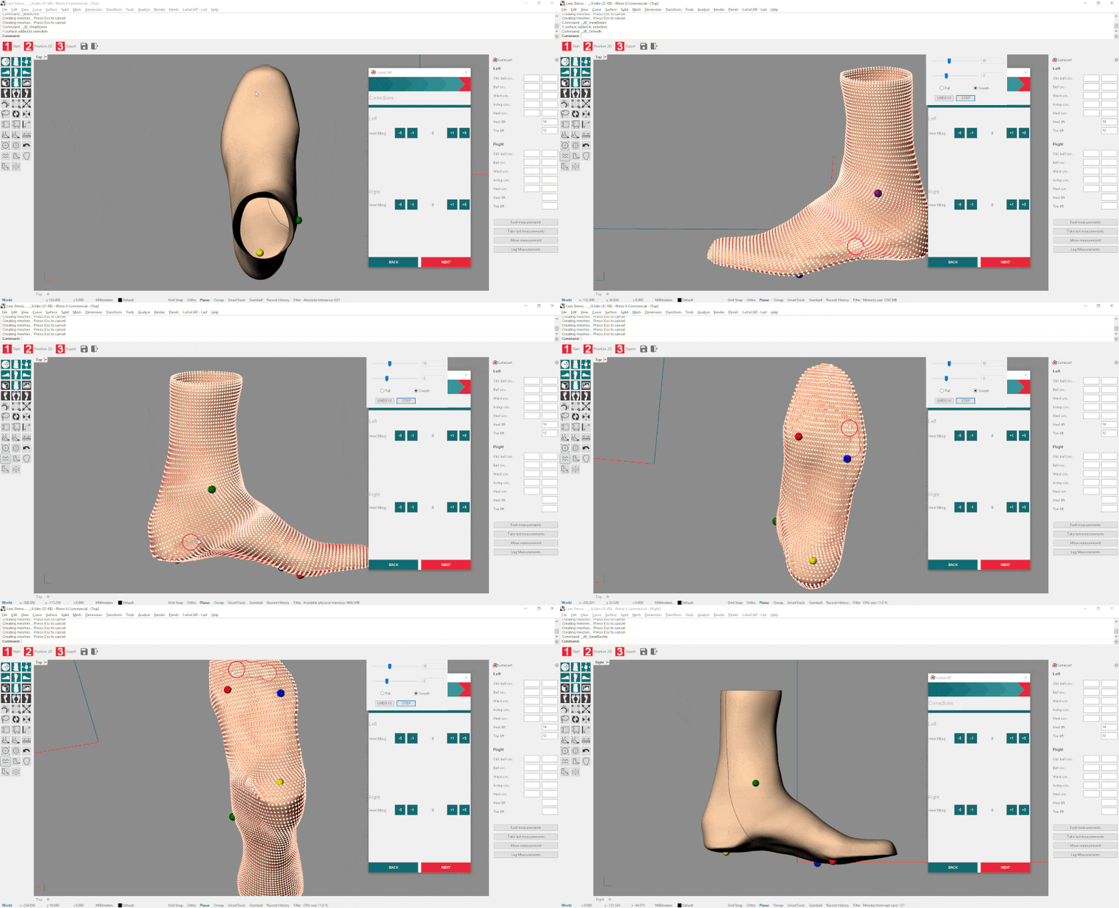
The 2 models are now merged and the basis of the last has been made.
- Transition between the 2 parts can be smoothed with our smooth tool
- Last height can be determined
- Circumferences can be checked
- Corrections can be made
For these actions please visit the corresponding tutorial page.
Step 9
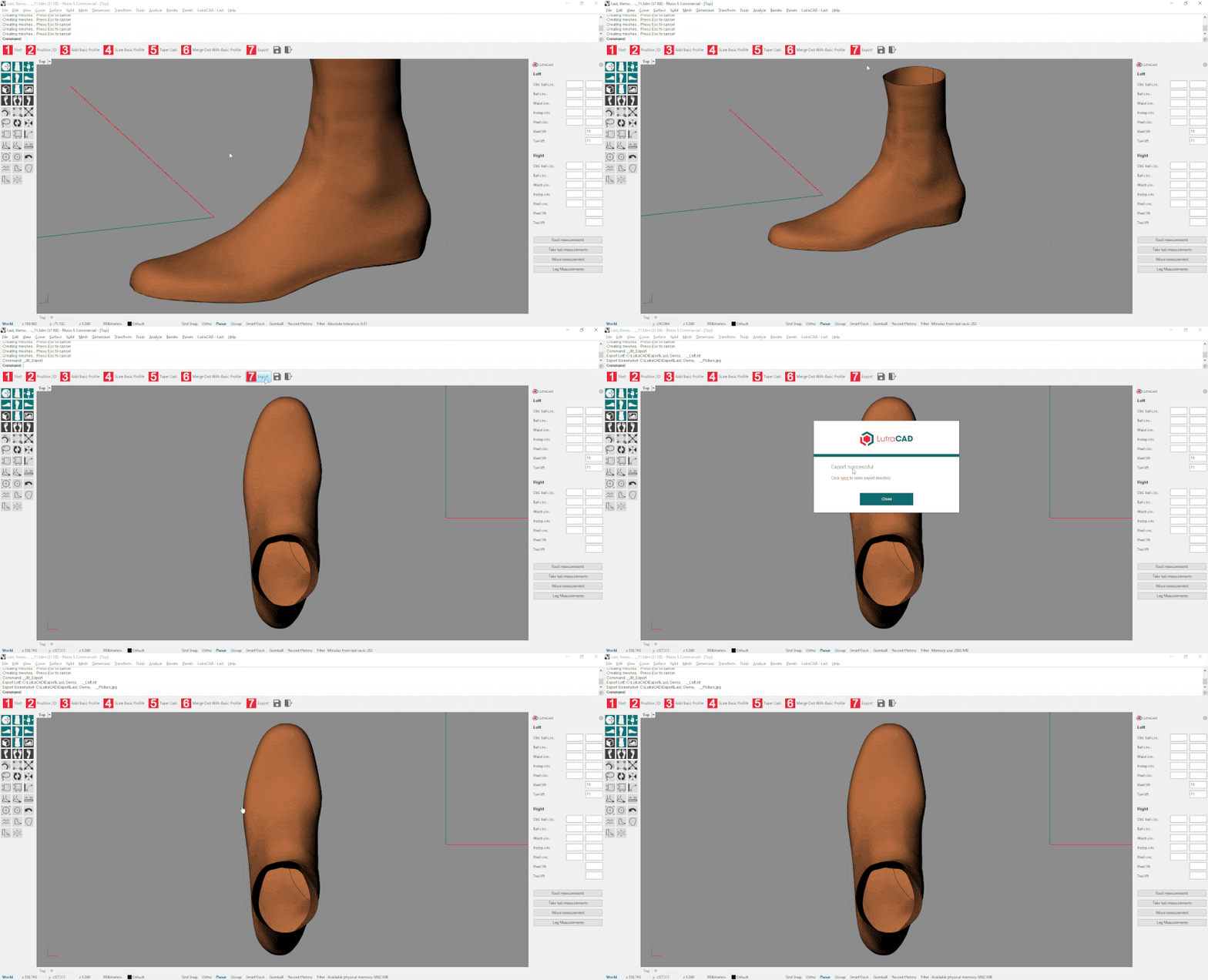
Now the lasts are ready to be exported for milling. By pressing the last step "Export" the lasts will be exported in separate files. By default they will be exported as STL files, but in the settings this can be changed to other formats.
Need help finding the right
anwer to your question?

